Hardware
The Trashformer is a small humanoid robot that is designed to patrol indoor environments and autonomously detect and pickup trash from the floor. This guide walks through the steps to deploy all of the necessary hardware onto the robot. NOTE: Substitute parts have not been fully tested with the Nvidia® provided example code.
● BIOLOID GP Humanoid (SKU: 901-0026-310) — Assembly Guide Below
● Nvidia® Jetson™ TX2 module (SKU: 900-83310-0001-000)
○ Substitute with Nvidia® Jetson™ TX1 (SKU: 900-82180-0001-000)
● Connect Tech Orbitty Carrier Board (SKU: ASG003)
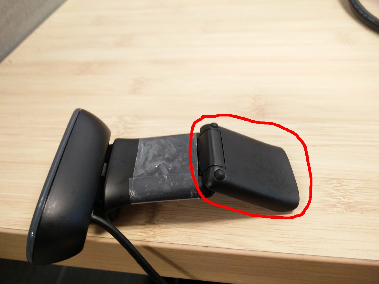
● Logitech C270 USB Webcam (SKU: 960-000694)
○ Many Substitutes — Any USB camera with support for OpenCV and Linux
● 2200 mAh Lithium-Polymer Battery (3 Cell 11.1 V) (20C minimum) (XT60 connector)
● Female XT60 Connector
● RP-SMA Antennas (x2) — Small recommended
● RP-SMA to I-PEX Cable (wifi)
● 18 AWG Wire
● 15 mm standoffs (x4)
● 7 mm standoffs (x4)
● Small (2 port) USB Hub
● Micro USB male to USB A female
● Solder and Soldering Iron
● Zip-ties of various sizes
Find the BIOLOID GP Assembly Guide Here (July 2017)
- Begin by assembling the Bioloid GP — follow the instructions provided by Robotis.
- Remove the back clamp of the Logitech C270 as it will not be needed.
Mounting the Jetson™ and the Camera
- Remove the “head” that comes default with the robot.
- This component is not necessary as it only houses an led.
- Ue large zip-ties to mount the camera onto the top of the humanoid where the head used to be.
- Screw the 15 mm standoffs into the predrilled holes on the top of the robot.
NOTE: Check to see if the Orbitty carrier board fits with the standoffs. If one of
the standoffs interferes with the GPIO pins, then remove it.

NOTE: The back standoffs will not fit the holes correctly; this is OK.
- Place the Orbitty on top of the robot with the ethernet port down and the two front holes aligned.
- Use the 7 mm standoffs to attach the orbitty to the robot. If the 15 mm standoffs do not align, then use nuts to attach the 7 mm standoffs.
- Attach the TX2 module to the Orbitty and screw it into the 7 mm standoffs.
Creating a Power Cable The Jetson and the original CM-530 microcontroller are powered by the same battery, so you need a Y power cable that connects the two to the battery.
- Remove the original battery from the humanoid and cut the two pin connector off from the battery. Cut close to the battery so that you have wire to work with later.
NOTE: Be careful not to short circuit the two exposed ends.
- Measure the amount of wire you will need to reach the Orbitty board from the battery. Make sure there is enough slack to attack the two pin connector for the CM-530. Cut the Length you need.
- Using the 14 AWG wire, solder the XT60 Female connector to the wire. It is recommended to use heat shrink to protect the exposed ends.
- In the middle of the 14 AWG wire, strip off some of the insulation. Solder the 2 pin CM-530 power connector.

- Strip the other ends of the 14 AWG wire to be inserted into Orbitty carrier board.
- The less excess wire, the easier it is for the robot to function without jamming.

Attaching Antennas
- Mounting the RP-SMA antennas is a personal choice, but this recommendation may reduce snagging and improve balance
- Using two small zip-ties, attach the antennas to the 7 mm standoffs.
