Welcome to Week 4 of ROS training exercises! We'll be learning about the coordinate frames, the IMU, and localization with dead reckoning by integrating IMU data.
IMU stands for Inertial Measurement Unit. A 9 DOF (degree of freedom) IMU measures accelerations, angular velocities, and magnetic field in all 3 axis by using an accelerometer, gyroscope, and magnetometer. This means that by using an IMU you will be able to tell your acceleration, angular velocity and heading.
One thing important when using the IMU is which coordinate frame the data is in. A coordinate frame is a reference to the coordinate system that is used for the data. For example, the IMU can measure accelerations in the x, y and z axes in the robot's coordinate frame, which is different from the world's coordinate frame.
A quick note: ROS has a REP 103 which defines conventions for coordinate frames. In particular, for bodies, X points forward, Y points left, and Z is pointing up, while for geographic locations X points east, Y points north, and Z points up.
An easy way to understand this is through an example: Let's say my IMU is mounted in the same direction as my robot. This means that when my IMU records an acceleration in the X direction, it means that the robot has accelerated forwards in the +X direction (cyan arrow). However, let's say that my robot is located at the point (2,1) in the world and is pointed north. In the robot's coordinate frame, the acceleration is in the +X direction. However, in the world's coordinate frame, because the robot is pointed north, which corresponds to the +Y direction, the acceleration is in the +Y direction.

We can perform localization with an IMU, to find out where we are. The simplest form of localization is called dead reckoning, where you determine your position by taking your previous position integrating your velocity over the elapsed time. In the case of our IMU though, since we get linear accelerations instead of linear velocities, we will need to integrate twice, and keep track of our velocities.
This means that our state, the things we need to keep track of, consists 4 things: Our x, y, heading and x-velocity.
Whenever a new IMU measurement comes, we can update our state using the basic Physics kinematics equations:
There are many ways of numerically integrating the data that yield more accurate results, this is just one simple way.
By doing this, we should be able to keep track of our position.
Let's try implementing dead reckoning in ROS with the simulation environment. Launch the environment with roslaunch:
roslaunch igvc_training_exercises week4.launchYou should see just a single turtle in the middle:

However, if you look at the rostopics, you'll see that there's now an imu topic /oswin/imu of type sensor_msgs/Imu.
Also, you can see that /oswin/ground_truth isn't there. We'll need to use dead reckoning to compute an estimate
of our pose.
Open up rqt_plot and graph the accelerations in the x axis, and then open up teleop_twist_keyboard as before:
rosrun teleop_twist_keyboard teleop_twist_keyboard.py cmd_vel:=/oswin/velocityMove around a bit and get a feel for what the accelerations from the IMU look like as you move around.
After you get a feel of what kind of data you're working with, its time to start writing some code. We'll be implementing this node in week4/main.cpp.
First thing to do is to write a subscriber that subscribes to the /oswin/imu topic. You should be familiar by now with
how to do this. ROS_INFO_STREAM the x acceleration and then run it to make sure that everything is working properly.
Afterwards, it's time to begin writing the actual dead reckoning. Before we start with implementing the kinematics equations earlier though, we need to setup the global variables representing our robot state that we'll need to keep track of in between callbacks. In addition, we'll need to keep track of the time which we received the last message in order to calculate the time in between each callback.
Afterwards, we can start implementing the dead reckoning algorithm in the callback. Here are the equations again, so that you don't need to scroll back up and find them:
Now that we have some basic localization, we need to publish this information so that we can visualize it, and so that
other nodes are able to use this information. ROS provides the nav_msgs::Odometry message type that describes the
robot's current location.
Create a publisher for the message type nav_msgs::Odometry on the topic /oswin/odometry, and then publish the
results of your dead reckoning. As always, don't forget to #include the message type.
If you forget Clion should yell at you as always.
When you get to filling in the nav_msgs::Odometry message, you'll notice that msg.pose.pose.orientation has four
different fields: x, y, z and w.
This is because the orientation field uses something called quaternions, which uses a 4D
vector to represent orientations in 3D space. If you're interested in the math of how quaternions work, feel free to
google them. There's also a neat video by 3Blue1Brown that explains it.
Don't worry if you don't understand how they work though. We can work with another representation of orientations called euler angles which are much simpler to understand and work with. The euler angles representation uses three numbers represent orientations: roll, pitch and yaw. If you're familiar with airplanes then this should be familiar to you: roll represents rotation around the x axis, pitch represents rotation around the y axis, and yaw represents rotation around the z axis.
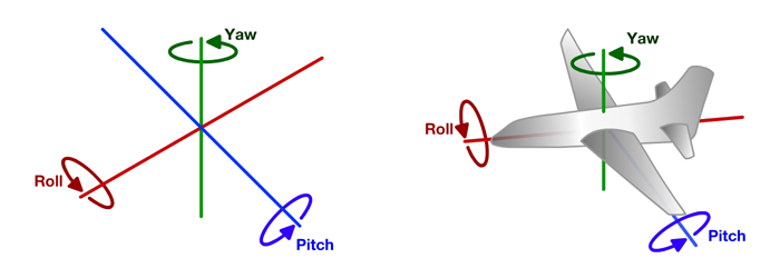
Because we're working in 2D, roll and pitch are 0, so the only angle we need to worry about is yaw.
In order to convert between euler angles and quaternions, the ROS built-in tf package provides a few useful methods
that we can use.
Add the following #include:
#include <tf/transform_datatypes.h>We can then use the tf::createQuaternionMsgFromYaw message to convert from yaw to a quaternion. This might look
something like:
odometry_msg.pose.pose.orientation = tf::createQuaternionMsgFromYaw(g_heading);One important field that we haven't gone over yet is the Header field on nav_msgs::Odometry. If you've finished the
Integral and Derivative controller from last week, then you probably have seen this before. Let's look at the definition
of the message from the ros documentation (again you can get here by googling ros header) or something:

The documentation should be pretty clear about what each of the fields are:
stamprefers to the timestamp of the message.frame_idon the other hand refers to the name of the coordinate frame of the message
If you recall at the beginning when we talked about coordinate frames, the
x acceleration is different depending on which coordinate frame you're talking about. In order to be clear about which
coordinate frame we're talking about, we can use this frame_id field to refer to a specific coordinate frame.
For example, if our world frame was called yeet, and we wanted to say that the position of our robot was in relation
to the Yeet frame, then we would set the frame_id field of the header to the value yeet:
nav_msgs::Odometry msg;
msg.header.frame_id = "yeet";
Of course, don't actually call your coordinate frame yeet. ROS defines a few standard coordinate frame names in
REP 105. Of those, we will be using the odom frame,
which is a world-fixed frame:
nav_msgs::Odometry msg;
msg.header.frame_id = "odom";We're finished with the algorithm, but we have no idea how well it works. To visualize the nav_msgs::Odometry message
we're publishing, we can use the rviz tool which ROS provides for visualizing the robot and other informations.
Open up rviz by running the rviz command:
rvizYou should see something similar to the screen below:

In order to visualize the nav_msgs::Odometry message that we're publishing:
- On the left in the
Global Optionssection change theFixed Frameto "odom", the value of theframe_idwe set earlier. - On the right, in the
Viewssection, change theTypetoTopDownOrthoto change the view from 3D to top down 2D. - Click the
Addbutton on the bottom left, select theBy topictab, and clickOdometryunder/oswin/odometry. You should now see a red arrow in the middle of your screen visualizing thenav_msgs::Odometrymessage that you're publishing.
Try moving the robot again using teleop_twist_keyboard. You should notice both the turtle in the simulator and the
red arrow moving, and hopefully the red arrows will be in the same location as the turtle in the simulator.
We're almost done. The last thing we need to do is to "broadcast" our transform (the position of our robot) to tf.
What is tf? We #include'ed a header file from tf earlier.
tf is a package that lets the user keep track of multiple coordinate frames over time. tf maintains the relationship between coordinate frames in a tree structure buffered in time, and lets the user transform points, vectors, etc between any two coordinate frames at any desired point in time.
In short, tf is a really nifty library for managing transforms. We've seen at the beginning how annoying coordinate
frames are. tf will allow us to very easily express data from one coordinate frame in another coordinate frame.
To do that though, tf needs to know where these coordinate frames are in. We can do that by broadcasting the
transform. To do that, we need to do three things:
Create a tf::TransformBroadcaster:
tf::TransformBroadcaster transform_broadcaster;We need to create a tf::TransformStamped variable in order to pass it to the tf::TransformBroadcaster that we just
made. Unfortunately, since this isn't a ROS message, this can't be looked up as easily as other messages. Thankfully,
Clion is here to save the day. Type in tf::TransformStamped, and then move your cursor over it. Hit Ctrl-Alt-B to go
to the definition of tf::TransformStamped. There will be a lot here, but what we want is the constructor. It
should look like this:
StampedTransform(const tf::Transform& input, const ros::Time& timestamp, const std::string & frame_id, const std::string & child_frame_id):
    tf::Transform (input), stamp_ ( timestamp ), frame_id_ (frame_id), child_frame_id_(child_frame_id){ };
Focusing only on the arguments, we can see that we need to pass 4 things:
tf::Transforminputros::Timetimestampstd::stringframe_idstd::stringchild_frame
Let's go through these one by one. tf::Transform represented the actual transform between the two coordinate
frames. The two most useful methods here are going to be:
.setOrigin(tf::Vector3 origin), which takes in an argument of typetf::Vector3and sets the origin, or position of the transform. Don't worry,tf::Vector3has a sane constructor - you pass in x, y and z coordinates in the constructor:tf::Transform transform; tf::Vector3 origin(1.0, 2.0, 3.0); transform.setOrigin(origin);
.setRotation(tf::Quaternion quaternion), which takes in an argument of typetf::Quaternionand sets the rotation of the transform. But theres one problem - oh noes, its in quaternions and not yaw! Don't worry, we can just do the same thing as we did earlier, except dotf::createQuaternionFromYawinstead oftf::createrQuaternionMsgFromYaw.tf::Transform transform; transform.setRotation(tf::createQuaternionFromYaw(1.57));
Next, ros::Time timestamp. This should be pretty self explanatory - it's the time at which this transform was
recorded. Why does there need to be a timestamp? For static transforms which don't change, such as the transform
from the imu to your robot, the timestamp doesn't matter. But for other transforms, such as the transform from the
world frame to your robot AKA your robot's position, the transform is different at different moments in time. We'll
make use of this next week. For this, we can just use the timestamp of the IMU message that we received.
Finally, the frame_id and child_frame arguments of type std::string. These should also be quite self explanatory:
They're the names of the frame and child frame for the transform you're trying to publish. For example, for our case,
we're trying to publish the transform of the robot frame in the world frame. This means that the frame_id,
(the reference frame we're currently in) is odom, while the child_frame (the reference frame we're trying to
describe) is oswin.
Finally, we call the .sendTransform function on the tf::TransformBroadcaster we created earlier. That's it.......
except not really. Most likely you've created tf::TransformBroadcaster in one of two ways:
- Created it as a global variable
- Created it in the callback
Both of these ways don't work. We can verify this by running rosrun tf tf_monitor, a tool which prints out all the
coordinate frame transforms that tf receives. If it were working, you would see something like:
Frame: oswin published by unknown_publisher Average Delay: 0.000244823 Max Delay: 0.000300968
But it's empty. What's the problem?
If you created it as a global variable, when you try running the node, it complains
that You must call ros::init() before creating the first NodeHandle. If you created it in the callback, no error
shows, but it still doesn't work.
The problem is that creating the tf::TransformBroadcaster needs some time to send the transform, kind of similar to
the situation with ros::Publisher during the first week. We can't really wait here though, since we need the
transforms as soon as possible (We want to know where we are right now, not like 1 second ago). So, we want to be
able to create the tf::TransformBroadcaster after we do ros::init, but only create it once.
One way we can do this is by using static local variables. Adding the static keyword to a local variable means that it will only be initialized once, the first time you come acros the statement, and it won't be destroyed when the scope. Also, when you come across the statement again, the variable won't be initialized again, and you'll have access to the same instance of the variable.
So, if we created tf::TransformBroadcaster as a static variable inside the callback like so:
void imuCallback(sensor_msgs::Imu msg)
{
  ...
  static tf::TrannsformBroadcaster transform_broadcaster;
}
then the first time the callback was called, which is after we do ros::init, the tf::TransformBroadcaster
variable will be initialized. Also, the next time the callback is called, the same instance of the variable will
still be there, and so there'll be enough time to send the transform. You should see that rosrun tf tf_monitor
is successfully able to show that the oswin frame is getting published to by your node.
We can visualize the tf frame we published to in rviz. Open up rviz, and then add a display of type tf.
You should be able to see two frames show up on the screen: "odom" and "oswin". Verify that your
tf::TransformBroadcaster is working properly by moving the turtle around. The "oswin" frame should also be moving.
And that's it for this week!
We learnt about:
- The IMU
- Measures acceleration, angular velocity, and orientation
- Has an accelerometer, gyroscope and magnetomer
- Coordinate Frames
- Coordinate Frames defines a set of direction relative to some object
- Understanding the basics of the REP 103 standards for Coordinate Frames
- Localization with Dead Reckoning
- Using kinematics equations to locate ourselves
- Implemented dead reckoning in ROS
nav_msgs::Odometrymessage type for odometry information- Turned something theoretical to something that was working again!
- rviz
- Use
rvizto visualize what's happening
- Use